
Table of Contents
ToggleIntroduction
In the medical, aerospace, and high-end automation sectors, engineering leaders and procurement experts frequently face a critical dilemma: key high-complexity shafts, bushings, or connector parts suffer from inconsistent batch quality, severe delivery delays, or performance shortfalls in final testing. This leads to stalled projects, uncontrolled costs, and lost market opportunities, undermining product launches and operational reliability.
The root cause is rarely the accuracy of a single machine. It lies in the traditional, fragmented supply chain collaboration model. Design, process planning, production, and quality control operate in different information silos, making systematic control over material behavior, microscopic geometric precision, and process stability nearly impossible. This article analyzes how precision CNC turning technology evolves beyond simple cutting to become a systemic solution integrating materials science, digital twins, and preventive quality engineering. It reveals how deep technical collaboration can fundamentally mitigate three core supply chain risks, ensuring predictable delivery of critical components.
How Do Information Silos Between Design and Production Inflate “Hidden Costs” Beyond the Quote?
Information silos between design and manufacturing are a primary source of hidden costs and project risk. Misalignment between 2D drawings and 3D models triggers clarification loops and rework. A lack of shared understanding about material heat treatment response can lead to batch scrap due to unexpected distortion during prototyping. Furthermore, opaque production tracking forces reactive schedule adjustments, inflating project management overhead. These indirect costs often far exceed the initial part price. Research clearly indicates that early feasibility analysis in the design phase can slash later engineering change costs by up to 30%, forming the economic foundation of a truly reliable partnership. To transform a high-complexity design into a stable, mass-produced component, a systematic approach is essential.
- The Cost of Ambiguous Design Intent and Rework Loops: When design intent is ambiguous, manufacturers must interpret. A missing tolerance, an undefined surface finish, or an unclear note on a 2D drawing forces production to pause for clarification. Each stop in the process adds days to the timeline. If an assumption is wrong, the result is scrap or rework, incurring costs for re-machining, new material, and lost machine time. This cycle is amplified when prototypes fail testing, revealing that the “as-designed” and “as-manufacturable” versions were never aligned, a direct consequence of working in silos rather than in an integrated product development framework.
- Material and Process Misalignment Leading to Catastrophic Waste: One of the most expensive silos exists between material specification and process execution. A designer may select a material for its ultimate tensile strength, unaware of its poor machinability or high distortion tendency during heat treatment. In production, this leads to extremely slow cutting speeds, rapid tool wear, and, worst of all, batches of parts warping beyond salvage after heat treat. The cost isn’t just the lost material; it’s the lost production slot, the delayed project, and the urgent search for a replacement material — all because material science and manufacturing process knowledge were not consulted during the design phase.
- The Management Overhead of an Opaque Supply Chain: When production is a “black box,” project managers are forced to build buffers into schedules and budgets. The inability to see real-time status — Is the material in-house? Has the first article been inspected? — leads to constant follow-up and emergency expediting. This reactive mode consumes valuable engineering and management time that should be spent on innovation. The hidden cost is the lost productivity of your team, who become supply chain firefighters instead of product developers. A transparent, collaborative workflow eliminates this overhead by providing shared visibility and proactive communication.
Why Does a “Perfect” Material on Paper Often Fail Under Real Cutting Stresses?
A material that looks perfect on a data sheet can fail catastrophically in production if its behavior under dynamic cutting stresses is not understood. The challenge is that data sheets list static properties in a controlled lab environment, not the complex, high-strain-rate, thermally active conditions of a CNC lathe. A standard stainless steel may have excellent corrosion resistance but can work-harden and gall during the turning of thin-walled features, ruining surface finish. A high-strength titanium alloy may see its residual stresses reconfigure during machining, causing parts to distort days after they are measured as “in spec.” Successfully machining advanced alloys requires deep integration of material science data with dynamic process parameters, a fusion that moves beyond simple selection to true material engineering.
1. The Disconnect Between Static Properties and Dynamic Machinability
Machinability — a material’s response to cutting — encompasses chip formation, heat generation, and tool wear. A data sheet doesn’t tell you that a certain precipitation-hardening stainless steel becomes extremely gummy and abrasive in its annealed state, leading to poor surface finish and short tool life. Nor does it predict that a high-silicon aluminum alloy will rapidly dull cutting edges. These real-world behaviors dictate cycle times, tooling costs, and part quality. Selecting a material without considering its machinability for the specific features (e.g., deep holes, thin walls) is a recipe for production headaches and cost overruns, directly impacting the viability of producing precision CNC turned parts.
2. Managing Thermal and Residual Stress Effects in Sensitive Alloys
Materials like titanium and Inconel are notorious for their low thermal conductivity and high chemical reactivity. The heat generated during cutting doesn’t dissipate quickly; it concentrates at the tool-workpiece interface, accelerating tool wear and potentially altering the material’s metallurgical structure at the surface. Furthermore, these alloys often contain significant residual stresses from their mill processing. The machining process itself can redistribute these stresses, causing the part to warp or distort over time, sometimes after it has passed initial inspection. Controlling this requires not just the right tool and coolant, but a deep understanding of stress states and often a specific sequence of roughing, semi-finishing, and stress-relief operations.
3. The Criticality of Heat Treatment Knowledge and Integration
For many high-performance components, the material’s final properties are achieved through heat treatment. However, the response to heat treatment is a critical part of the material selection. A steel chosen for its high core strength might have poor hardenability, resulting in inconsistent case depth or soft spots. Another might be prone to excessive growth or distortion during carburizing. The manufacturing partner must understand the full cycle: how the material will be machined in its pre-treated state, how it will distort during treatment, and what final machining (grinding, honing) is needed to achieve final dimensions. This holistic view is essential for materials used in high-end equipment cores, where performance is non-negotiable.
Are Your Part’s Most Critical Features Also Its Most “Unmanufacturable” in Volume?
Often, the most functionally critical features of a part are also the most challenging to produce consistently at volume. A micro-hole with a 10:1 depth-to-diameter ratio needed for lubrication may be achievable in a prototype with extreme care, but maintaining its diameter tolerance, straightness, and surface finish across 10,000 pieces is a different challenge. Similarly, a miniature internal Acme thread for precise adjustment must engage smoothly in every unit. These features become bottlenecks that dictate yield rates and costs. Designing for precision volume manufacturing requires anticipating these challenges and incorporating features that enhance process capability, such as adding tool relief or strategic datum surfaces. Mastering these principles is the foundation for executing reliable precision CNC turning solutions.
1. The Scalability Challenge of High-Aspect-Ratio and Micro Features
Deep, small-diameter holes and long, thin walls are anathema to stable, high-volume machining. As tool length increases, rigidity plummets, leading to chatter, taper, and tool breakage. In volume production, this translates to high scrap rates and frequent tool changes. The solution lies in both design and process. Design can sometimes allow for a stepped diameter or a relief at the bottom of a hole. The process must employ specialized tooling (e.g., coolant-through drills), pecking cycles, and potentially secondary operations like gun drilling or reaming. The goal is to design a feature that can be produced with a capable and stable process, not just a possible one.
2. Maintaining Consistency in Complex Contours and Thread Forms
Complex profiles, such as those found on cam surfaces or specialty thread forms (e.g., ball screws), require precise synchronization of multiple machine axes. Any wear in the machine’s ball screws, thermal growth, or tool deflection will be imprinted on the part. In volume production, maintaining this over thousands of cycles requires a machine in peak condition, a robust tool wear monitoring system, and often, a post-process inspection of the critical profile. Designing with slightly more generous tolerances on non-critical portions of the contour or specifying a standard thread form where possible can dramatically improve manufacturability and yield without sacrificing function.
3. Designing for Stable Fixturing and Datum Strategy
A part that is difficult to hold securely will be difficult to machine consistently. Features on multiple sides often require multiple setups, introducing error each time the part is re-clamped. A smart design incorporates machining datums — flat surfaces, concentric diameters, or precision ground faces — that can be used to accurately locate the part in the fixture for every operation. For volume production, designing for a single setup or a palletized fixture system that maintains location across operations is ideal. This minimizes handling, reduces error, and speeds up the CNC turning process, directly impacting cost and throughput. The part design should facilitate, not hinder, a logical and repeatable manufacturing sequence.
How Can a Digital Thread from CAD to CMM Eliminate “Surprise” Defects at Delivery?
The digital thread is the seamless flow of data from the original CAD model through CAM programming, machine execution, and final inspection. It is the antidote to “surprise” defects at delivery. When the CAD model is the single source of truth, the CAM program generates optimal toolpaths, the CNC machine executes them while collecting performance data, and the CMM inspects the part against the original model, quality becomes predictable. This closed-loop system enables in-process compensation for tool wear and thermal effects, moving quality control from a final checkpoint to an embedded characteristic of the process itself. It is the technological foundation of a smart factory, ensuring that what is designed is what is built, every time.
1. Model-Based Definition and Automated Programming
The journey begins with a 3D CAD model containing all necessary Product Manufacturing Information (PMI) — dimensions, tolerances, and notes. This model-based definition (MBD) eliminates ambiguity from 2D drawings. Advanced CAM software then uses this model to automatically generate efficient, collision-free toolpaths, significantly reducing programming time and human error. The software can simulate the entire machining process, identifying potential issues like tool holder collisions or insufficient material removal before any metal is cut. This digital prototyping de-risks the program before it ever reaches the shop floor.
2. In-Process Monitoring and Adaptive Control
On the machine, the digital thread comes alive with sensors and probes. On-machine probing can measure a critical diameter after roughing and automatically update the tool offset for the finishing pass, compensating for tool wear or part deflection. Vibration and power monitoring can detect the onset of chatter or a dull tool, allowing the system to adjust parameters or alert an operator. This real-time, data-driven feedback loop creates an adaptive machining environment. The machine is no longer a blind executor of code; it is an intelligent participant in making a good part, capable of making micro-corrections to stay on course.
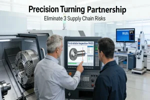
3. First-Article Validation and Data-Driven Traceability
Upon completion, the part is measured on a Coordinate Measuring Machine (CMM). Instead of manually programming the CMM, the inspection plan is generated directly from the CAD model’s PMI. The CMM produces a comprehensive report, often a color-cated deviation map showing exactly how the physical part differs from the nominal model. This objective data is linked to the part’s serial number, the tooling used, and the machine data, creating a full digital twin of the part’s manufacturing history. This immutable record provides undeniable proof of conformity, facilitates rapid root-cause analysis for any deviation, and fulfills the stringent traceability requirements of industries like aerospace and medical devices. It transforms quality from a claim into a verifiable dataset.
From Surgical Robotics to Satellite Actuators: What Does a Risk-Mitigated Success Story Look Like?
A manufacturer’s high-precision optical component project was plagued by a 65% yield and 8-week delays. After a systematic DFM overhaul, the team redesigned thread geometry, switched to specialized tooling, and implemented SPC controls, enabling production to consistently deliver at a 99.8% yield and 22% lower cost in just 3 weeks — transforming a critical failure point into a predictable process and securing a successful product launch.
- Diagnosing Systemic Failure in the Initial State: The project was in crisis. Parts failed thread gauge checks, had inconsistent engagement torque, and suffered from high surface roughness. The traditional supplier relationship was transactional: “make this print.” There was no collaboration on the thread design’s vulnerability, no deep dive into why the standard carbide tools were failing after 10 parts, and no visibility into the production process to understand the source of variation. The high scrap rate and constant expediting were symptoms of a fragmented, non-collaborative approach where design and manufacturing were disconnected.
- Implementing the Integrated Technical Solution: The solution required breaking down silos. The client’s engineers and the manufacturing partner’s application team worked as one unit. The DFM session resulted in a more robust thread design. The manufacturing partner’s materials and tooling experts specified a PCD tool, which, while more expensive upfront, lasted for thousands of parts with no wear, ensuring consistent finish. Their process engineers designed a machining sequence that included a stress-relief operation and integrated probing for tool compensation. Finally, their quality team set up SPC at the machine, so operators could see trends in real-time and make adjustments before making bad parts.
- Quantifying the Business and Technical Outcomes: The outcomes were measured in hard business metrics: Yield increased from 65% to 99.8%, a direct reflection of process control. Lead time reduced from 8 to 3 weeks, a result of eliminating rework loops and implementing a predictable flow. Cost per part decreased by 22% despite a more expensive tool, due to the elimination of scrap and reduced touch labor. Technically, the thread engagement torque became highly consistent, and the surface finish improved dramatically. The component was no longer a variable; it was a solved problem, allowing the client to focus their engineering resources on system-level innovation, not component-level firefighting.
What Constitutes a True Manufacturing Partnership Versus a Transactional Supplier?
A true manufacturing partnership is a strategic alliance built on shared risk, deep technical collaboration, and a commitment to mutual success. It transcends the transactional “send a quote, get parts” model. A partner possesses a preventive quality culture, often codified in standards like IATF 16949, and invests in understanding the why behind your design. Their engineering team acts as an extension of your own, providing proactive DFM feedback and solving complex problems from material science to metrology. They offer transparency and possess the systemic capability to guide a project from prototype to volume production seamlessly. For components critical to your product’s core performance, this partnership transforms your supply chain from a cost center into a source of competitive advantage. Therefore, the foundation of a true partnership is systemic capability. A supplier whose value lies in deep engineering collaboration and a digital quality loop delivers reliable solutions that transcend simple part production.
1. A Culture of Prevention, Not Detection
A transactional supplier inspects quality at the end, hoping to catch bad parts. A true partner builds quality in from the start. This is evidenced by their quality management system. Do they practice Advanced Product Quality Planning (APAP)? Do they use Failure Mode and Effects Analysis (FMEA) to proactively identify and mitigate risks in the process? A partner with a IATF 16949 certification is audited on these very practices. Their culture is focused on preventing errors through robust process design and control, not just finding them after the fact. This mindset aligns perfectly with the needs of high-stakes industries where failure is not an option.
2. Depth of Technical Collaboration and Problem-Solving
The difference is revealed when challenges arise. A transactional supplier may say, “We can’t hold that tolerance,” or “That material is too difficult.” A partner will say, “To hold that tolerance, we recommend this alternative geometry or this specific tooling strategy,” or “For that material, we have a proven parameter set and a special coolant protocol.” They bring application engineering expertise to the table. They are willing to run tests, share data, and co-develop solutions. This depth transforms them from a vendor into a technical business development asset, helping you innovate and de-risk your designs.
3. Strategic Alignment for the Product Lifecycle
Finally, assess the partner’s strategic fit for your entire product journey. Do they have the flexible capacity for agile prototyping and the scalable systems for high-volume production? Is their communication proactive and transparent? The ideal partner is invested in your long-term success. They help you navigate not just the first order, but the transition from 10 prototypes to 10,000 production units, ensuring consistency, reliability, and continuous improvement at every stage. This holistic, strategic alignment is what ultimately defines a partner capable of delivering precision turned parts that become a reliable foundation for your products.
Conclusion
Precision CNC turning for high-complexity components has evolved from a dimensional shaping capability into a comprehensive risk mitigation strategy. By dismantling information silos, mastering the dynamic interplay between material science and cutting processes, designing for volume manufacturability, and implementing a robust digital quality thread, engineering teams can transform critical component supply from a major project variable into a pillar of predictable performance. This systemic approach, executed in partnership with a manufacturer possessing deep engineering and quality capabilities, is how leaders build resilient, innovative, and competitive products in the most demanding markets.
FAQs
Q: What surface finish and tolerances are realistically achievable with precision CNC turning for production batches?
A: In a controlled production environment, precision CNC turning can consistently achieve surface finishes of Ra 0.4 μm or better. Dimensional tolerances for diameters can reliably reach ±0.0125 mm, with geometric tolerances like roundness held within 0.0025 mm. Consistency across batches depends on high-stability machines, rigorous tool management, in-process gauging, and a preventive quality system, not just a single setup’s capability.
Q: How does the choice between a Swiss-type lathe and a standard CNC lathe impact the machining of complex, small-diameter shafts?
A: Swiss-type lathes excel with long, slender parts (high L/D ratio) by supporting the bar close to the cut with a guide bushing, minimizing deflection. They allow complex front and back working in one chucking, ideal for medical pins. Standard CNC lathes are more cost-effective for shorter parts or those with complexity concentrated on one end. The choice hinges on part geometry, feature location, and required concentricity along the shaft’s length.
Q: What are the primary cost drivers when moving a precision turned part from prototype to high-volume production?
A: Cost drivers shift dramatically. Prototypes are dominated by programming, setup, and low material utilization. High-volume production focuses on optimizing piece cycle time, managing tooling cost-per-edge, implementing automated handling, and statistical process control (SPC) to maintain yield. A strategic partner designs the process for scalability from the start, often investing in dedicated fixtures and tooling to drive down the per-part cost.
Q: Can precision turned parts be effectively inspected without a Coordinate Measuring Machine (CMM)?
A: Basic dimensions can be checked with hand tools. However, verifying true geometric tolerances (roundness, concentricity) and complex contours requires a CMM. It provides a definitive, data-driven comparison to the 3D CAD model. For high-volume production, automated vision or laser systems may be used for 100% inspection, but the CMM remains the gold standard for first-article validation and audits, ensuring compliance with the digital thread.
Q: How do you manage the challenge of heat dissipation and tool wear when turning difficult materials like Inconel or titanium?
A: Machining high-temperature alloys requires a systematic approach: Specialized tool geometries and substrates to withstand heat and abrasion. High-pressure coolant directed at the cutting interface for temperature and chip control. Optimized cutting parameters using lower speeds and consistent feeds. Aggressive tool life management replaces inserts based on monitored wear, not failure, to prevent part damage and ensure consistent quality and dimensional stability.
Author Bio
The author is an expert specializing in the manufacturing of highly complex rotating components, boasting over 15 years of extensive experience dedicated to helping clients resolve challenges related to production consistency for mission-critical parts. Their expertise is underpinned by JS Precision — a precision engineering partner whose team operates under a rigorous, certified management system encompassing ISO 9001, IATF 16949, and AS9100D standards — thereby ensuring systematic quality management and end-to-end traceability. If you are currently planning your next critical project involving shafts or bushings and require professional DFM analysis and precise quotation, we invite you to explore their comprehensive CNC turning capabilities and obtain a customized engineering assessment.


